This is a (somewhat rambling) description of our residential, 4 kilowatt, grid-tied, photovoltaic power generation system. If you do better with pictures only, go here.
The site, our house, is a standard, wood-frame, residential home built in the 1950s. It is located in the foothills near Los Angeles about 10 miles from Pasadena, CA (and thus CalTech/JPL, where I work). There are good things and bad about this site with respect to building and installing a PV system.
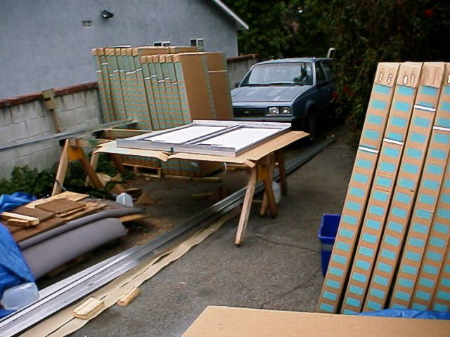
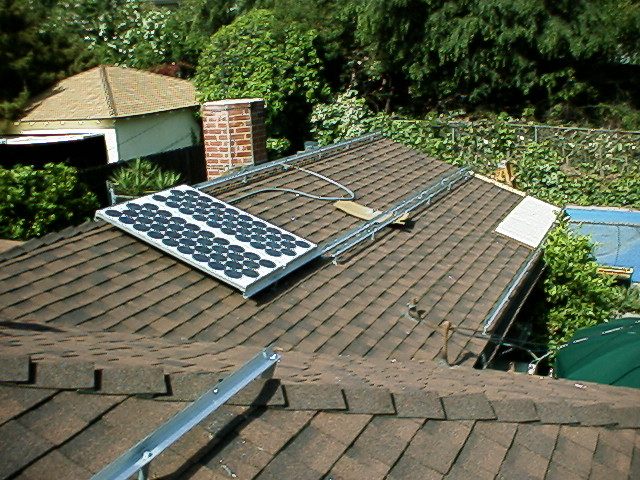
Ultimately we decided to mount the solar panels rigidly on the south-facing sections of our house roof. We have 40x100-watt modules (of 36 cells each) attached to a sturdy frame about 8-inches above, and parallel to, the roof. Each panel is nominal 17V open-circuit, and we have paired them up to give us a "24V" system. We have divided the total array into 4 sections, each having 4-6 24V module pairs, depending on the size of that section of the roof. The wires from each module pair run to a junction box for that section, and from the junction boxes down to the inverter cabinet on the ground.
Once in the inverter cabinet the wires from the 4 sections go through a ground fault interrupter and then through a set of DC breakers and finally to the batteries. The breakers allow us to disconnect the array sections from the batteries (for servicing, etc). Between the batteries and the inverters are 2 more DC breakers, one per inverter, that likewise allow us to shut down the inverters.
Also connected to the inverters is the AC input from the public power grid, as well as the AC output to the house loads. The inverter manages the power from these sources, keeping the DC voltage in a range that makes the batteries happy and supplying AC power to the house loads. If the loads require more power than is available from the panels, enough is pulled in from the public grid to make up the difference. If the loads are not fully using the solar power, the "extra" is pumped onto the public grid, running the meter backwards.
In normal operation the batteries in our system are not used. Only when the grid power goes away completely do the inverters draw on the batteries. This keeps the batteries from constantly going through the discharge/charge cycle, increasing their life and minimizing maintenance, while at the same time protecting us (OK, our computers) from brownouts and (most) blackouts.
In fact, the open-circuit voltage of one of the mini-arrays floats at almost twice that - around 40V (regardless of light level, oddly enough) - but as soon as you attach them to a reasonable load (or a battery) they lose 6-8 volts. They'll lose even more if there are clouds or high temperatures. Once installed in the circuit with the inverters, the inverters will draw down this voltage even further to maintain correct voltage for the batteries. Thus this configuration is correct, even though the numbers don't seem to add up initially.
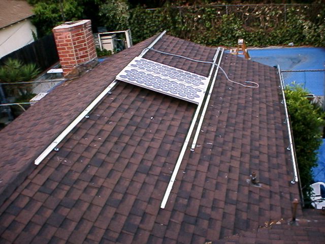
In the middle of this picture (on the sawhorses) are two modules in the process of being wired into one of these mini-arrays and having some pieces of angle-aluminum bolted on. These brackets not only hold the arrays together, but they also serve to attach the mini-array to the mount points on the roof. Here's a couple pictures of the first of these mini-arrays up on the roof. The arrays are connected to the roof by parallel lengths of angle-aluminum.
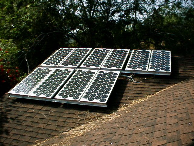
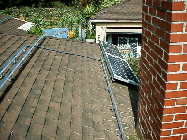
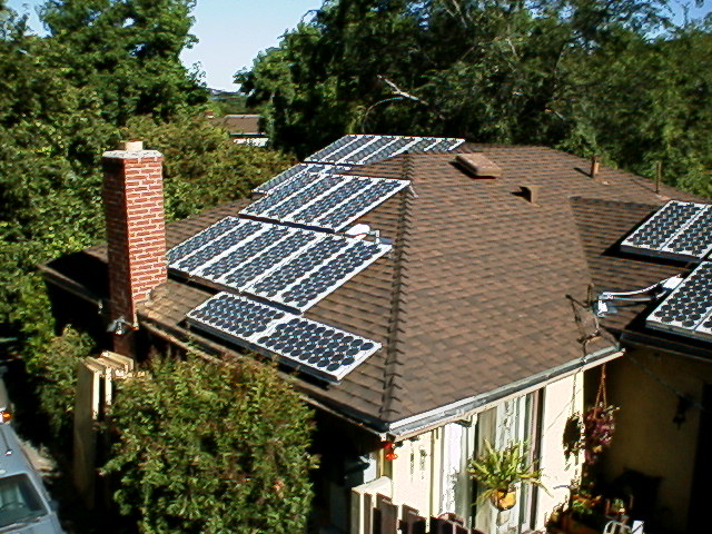
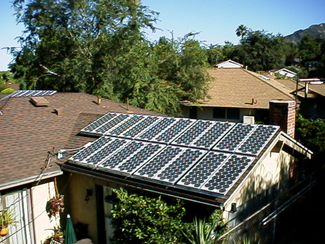
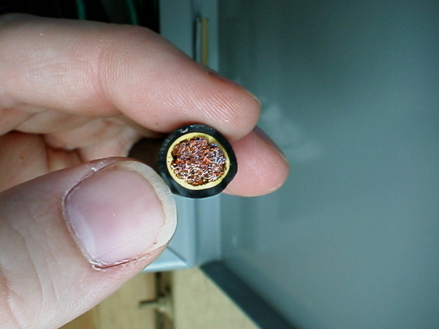
Here's another picture I took the next day that shows the scheme a little better. We have arrays on 3 sections of our roof, the front (west) of the house, the south, and the east. The east array is actually two arrays, but since they're all connected in parallel to the inverters the distinction is mostly semantic. Once the panels are all installed, the conduit and combiner boxes attached, and all the wires are connected everything looks like this and this. (That wire running from the lower-left corner of the second picture down to the roof is the incoming grid-power cable coming down from a telephone pole.)
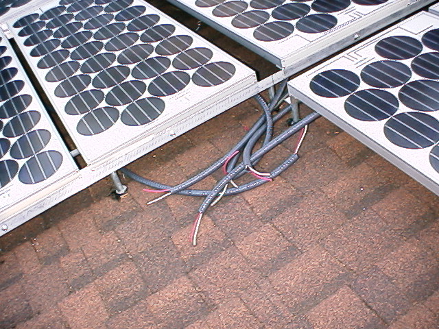
Once the arrays have been bolted in place, the wires coming from the mini-arrays on each segment are routed into a combiner box. The combiner boxes connect all the power-carrying wires together so that the output of all panels in a segment comes out of the combiner box as one large cable carrying up to (in our case) ~1K watts @24VDC. In our design we have 4 combiner boxes, so we have 4 of these wires plus their corresponding ground wires. Also going into the combiner boxes is an isolated chassis-ground wire from the metal frame of the panels (actually it's attached to the rails, which are attached to the frame on the panels). All the wires go down through conduit to the inverters' electrical panel.
Once they get to the electrical panel, the first thing that happens is that the power and frame-ground goes through a ground-fault protector. Then the 4 power-carrying wires each go through their own independent breakers so we can shut them down individually if we need to (to work on them for example). After the breakers they get combined into one line that goes into the batteries and to the DC side of the inverters.
Each Trace 4024 inverter puts out 120VAC. We have two because we need 240AC. We need 240VAC for two reasons. One is because we have two 240VAC loads that we want to power, one of which is our air-conditioning (and there is something quite satisfying about powering your AC with the same sun that is making things so hot). The other (and main [sorry again]) reason is because we have 240VAC coming in from the public power grid.
The inverters have the ability to synchronize their outputs so that they can drive 240VAC loads, in addition to 120VAC loads. By connecting the inverters together we can connect one inverter to each of the two legs of the 240VAC input from the public power grid. This way we can drive both our 240VAC loads and our 120VAC loads. Connecting the inverters in this way also gives us the ability, if the batteries are fully charged and the solar panels are putting out more power than the house loads require, to push our excess power onto the public grid. (Yes! This will run the meter backwards.)
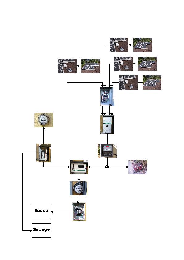
If that's all clear as mud, maybe this will help:
The inverters are packed with other features, some of which we will either not use or will use only very rarely in our installation (such as a gasoline generator input). One thing we will do in "stage II" after we get the basic system up is attach something to the "remote control port". Initially we will check status and control the operation of the unit(s) from the front panel, but this port allows us to connect to and manage the functions of the unit from a computer serial port. We are hoping to link this capability to our household web server to display the inverters' status on any computer in our house, or even on remote computers over the web.
HOWEVER, we are currently considering building our own
microcontroller-based data logging system to keep tabs on the whole
system, instead of just the inverters. More as this plan(?) develops.
The DC power from the solar panels is connected to the batteries and to
the DC-in on the inverters. This puts the inverters at the center of
the system where it can automatically manage the various power sources
and sinks.
Still having problems? Check out this diagram.
Under normal circumstances we will have access to grid power so we will
not use the batteries, and need not use the solar panels, though of
course we will to offset our electric bill. Basically we are using the
grid itself as a giant bank of batteries. The "local bank" of batteries
is just there to stabilize the solar output voltage for the inverters,
and to provide a sort of whole-house UPS (with 36ms transfer time) in
case the grid goes out. The inverter automatically manages this
potentially (sorry) complex mix of power sources and sinks so we can
behave just as we did before installing the solar system. We like the
inverters.
One thing that we have done to facilitate managing the power consumption
in this situation is to go through the house and locate all the "phantom
loads" - the "wall wart"-type power supplies and appliances such as VCRs
and TVs that have electronics that continue to draw power even when
"off". (Our entertainment center alone draws 1.3A @ 120v even when
everything is supposedly off!) These we have put on power strips so
that we can shut them off completely if necessary.
Needless to say, in the future we will pay more attention to such things
when purchasing electronic equipment to try to avoid adding any more of
these sorts of phantom loads to our system in the first place.
Manufacturers take note!
(In the past there has only been 1 outage lasting more than 1 day
in the 20+ years that we have lived here and it was caused by a
substation power transformer literally blowing up. Even so, we do have
a gasoline generator that we can use to keep food in the freezer from
thawing if things degrade to that degree, and of course we will also
have several hours of solar input every day, even on cloudy days
and in the winter.. at least enough to handle critical loads.)
Actually, one of our biggest concerns at this point is overcharging the
batteries. Under normal conditions, i.e. with the public grid powered
and inverters connected to it, any excess power is dumped to the grid.
However, when there is a grid failure the inverters are required
to automatically disconnect themselves from the grid for safety reasons.
This means that there is no place to dump any excess, and if the panels
remained connected to the batteries in this situation the batteries
could easily be overcharged.
Remember, the battery output and solar panel output are both attached in
parallel to the inverters' DC side. The only way that the inverter(s)
can control the voltage in this situation is by drawing off any excess
and dumping it somewhere. The only places where it can be dumped is
into the house loads and onto the grid. We could deal with this
"manually" by running around and turning on (yes, on) appliances during
a grid power failure, or by manually disconnecting one or more arrays at
the input to the electrical panel that feeds the batteries and
inverters, but this would be a PITA not to mention comical.
Fortunately the inverters also have several general-purpose relays that
we can use. They are triggered by battery voltage so we can potentially
rig them so that if the batteries are full, either power is shunted to a
water heater or something, or else the panel output is simply
disconnected. When the battery voltage falls sufficiently the relay(s)
can reconfigure things to charge the batteries from the panels again.
Did I mention we like the inverters?
Currently we simply have the relays rigged to sound an alarm when the
battery voltage rises above a certain threshold. At that point we can
manually disconnect one or more arrays to bring the solar input in line
with house loads. As a final fail-safe measure we also have a solenoid
connected in such a way as to (mechanically) trip the GFI breaker if the
battery voltage continues to rise. Reconnecting the solar inputs in
this case requires manually resetting the switch.
The inverters actually have two settings for each relay, the voltage to
trip on at and a "hysteresis" value that can be set independently to
trip off. This is good because it means that we can set the relay to
disconnect a panel section above a certain voltage, say 26V, but not go
on again until the voltage has dropped to a couple volts below that.
This keeps the relays from "chattering" if the voltage fluctuates in a
range around the threshold, which it will do as soon as the section gets
disconnected for example, or as clouds move in front of the sun. This
in turn keeps the wear on the mechanical parts to a minimum.
As I mentioned, we have set each of the 4 relays to trip at slightly different
voltages. This means that as the house loads and/or solar power from the
panels varies some of the panel sections will remain connected. Ideally we
would like the power output of the solar panels to exactly offset the house
loads so that the batteries are neither charging nor discharging. Practically
speaking the relay arrangement is somewhat less than ideal, but as a fallback
capability for exceptional situations it does the job. It's not nearly as
efficient at matching loads to power production as would be the case if the
grid were connected, but it's a lot better than the (still in place)
all-or-nothing GFI breaker solution we had originally.
Also, whereas the GFI needed to be manually reset each time, this new
configuration is completely automatic. If the grid loses power, the
inverters automatically disconnect from the grid, the battery voltage
starts to climb, and the relays trip the first panel section off. If
the battery voltage continues to climb the relays will disconnect
another section, and another, and finally the last section, at which
point no power will be getting to the batteries.
If the house loads draw down the voltage enough or the sun goes behind a
cloud, the relays reconnect each section one by one to bring the voltage
back up. Because the voltage thresholds are different for the different
relays, it's entirely possible to have, say, two panel sections
connected and the other two disconnected, and for sections to be
connected and disconnected as necessary to maintain battery voltage as
the grid outage continues, and the solar input and house loads
fluctuate.
When Edison fixes the problem and the grid powers back up, the inverters
automatically reconnect to the grid and the inverter pulls the DC
voltage back down by shunting power to the grid. If the DC voltage
remains nominal, the relays pulse all the solenoids to flip the breakers
on, and the breakers reconnect all the panels, enabling the maximum
solar output to be shunted to (or "stored on") the public power grid.
We do like the inverters. :)
This is something we probably should have included in the original design but
didn't. It hasn't caused us any real issues, but it might have been a problem
if we had had trouble with the inverters. If that had happened and we'd had to
shut down the system then the house would have gone dark because the house was
hardwired to the inverter output. This even if the grid was working fine! Not
a situation you want to be in. This way if the grid has trouble we put the
house on the solar system, and if the solar system has problems we flip the
switch over to the direct-to-grid connection. Of course the nominal
configuration is to leave the switch in the position that connects the house to
the solar system.
The charge controllers are Schneider Electric (formerly Xantrex) model C60
controllers, and we put one on each of the 4 array sections. They were about
$120 each, and we had to add another electrical cabinet to hold them, so that
plus wiring, conduit, and electician's time added about $800 to the system cost
(maybe 1 year to the payback time), but being solid-state they should be much
more reliable.
(As an aside, I noticed while shopping that prices for PV parts have really come
down in the last few years. I haven't done any rigorous design pricing, but at
a guess I'd say I might be able to put together a system with the same specs
and output as ours for at least 30% less, maybe more. Factor in 10 years of
inflation and it might be closer to half the cost in real terms. At least
something seems to be going the right direction!)
So what was the price of this whole setup? By far the biggest expenses
were the panels. The panels individually cost $425, and we have 40 of them for
a total of nearly $17,000. The inverters together cost nearly $5,000. Hired
labor (electricians, etc.) was another $5-6k. The remainder of the $31870.63
price includes the DC disconnect boxes, the GFI, batteries, conduit, combiner
boxes, wire, fuses, various mechanical parts (mounting hardware, etc.),
permit/inspection fees, and warranties.
Fortunately California has a program that rebates up to half of the price of a
solar installation such as ours. Thus, of the nearly $32k we initially paid,
we applied for and received just over $15k back from the state. This brought
our total cost for the system down to just under $17k.
If you would like to see a more detailed breakdown of costs (and suppliers) you
can check out this PDF.
That's just the initial cost of the system though.. what about the recurring
and TCO costs? Those are tricky questions because there are a number of
unknowns. Let's start with the knowns.
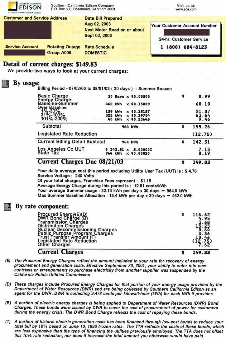
First of all is our electric bill. According to the last electric bill before
we switched to net metering, the "marginal $/KWhr" (the cost of an additional
KWhr) of electricity was as high as $0.23-0.26/KWhr, depending on the time of
year (winter rates are lower than summer rates), and which "tier" we fell into.
(Here is our actual last
month's electric bill from SoCal Edison before we switched.)
Second is the output of our solar system. For monitoring purposes we have
installed two additional electricity meters, similar to the one that the power
company reads to determine our bill. One monitors how much the house loads
take, and the other is for the garage loads. Since the "official" power
company meter shows the net power actually coming into the system, the
production of the solar panels can be obtained by adding the garage and house
meters, then subtracting the power company's meter. (Technically this also
includes inefficiencies for things like charging the batteries and inverter
DC->AC conversion, but for cost calculations this is typically what you want.)
Being solar, our production varies based on time of year, the weather, etc.,
but for last year our actual overall production was 4404.9 KWhr. Multiplied by
$0.23-0.26/KWhr, this gives an estimate of between $1013 and $1145 that we
saved last year.
Unfortunately it isn't that simple. The true amount saved will actually be a
bit less, since even though most of our "top tier" usage is in the expensive
summer months, some of it occurs during the winter and gets the lower rates.
On the other hand, the solar output is less in the winter, so we have to
rely more on "imported" electricity from the grid, and it is thus easier to
reach the more expensive rate tiers in winter. (Even though the most-expensive
tier in winter is less than half what it is in summer.)
Confused? So were we. The desire to get away from that sort of thing was one
of the factors in our decision to install the PV system. But I digress.
Anyway, sorting all that out is a bit of a trick, but on average we wind up
saving about $900-1000 per year. One might be tempted to divide the $16,660
cost of our PV system by $1000 and come up with an estimated "break-even" time
of around 17 years.
Since there are very few moving parts to our system, maintenance costs are
basically limited to periodic replacement of the batteries. The battery bank
cost nearly $800, but since we don't often cycle them they should last much
longer than would be typical for an off-grid PV system. We're estimating that
we will have to replace them once every 7-10 years. If new power storage
technology comes out, maybe that can be extended. If grid power becomes more
unreliable and we have to cycle them more we might have to replace them more
often.
(NOTE: we did replace the batteries once, in 2007(?). It cost about $850.)
The solar panels will degrade over time, but they are guaranteed by the
manufacturer to produce at least 80% of their initial output for at least 25
years. The inverters are solid-state and should last for many years as well.
They are only warranted for 5 years however, so it is possible we would have to
pay to replace them roughly that often. Trace had a very good reputation
however, and Xantrex seems to be keeping up the tradition. We would be
somewhat surprised if the inverter model we're using didn't last at -least- 10
years or more.
As I type this, the system has been operating for nearly 4 years. In that time
we have not had a significant failure of any part of the system. We had a
couple "operator errors" in the early days that caused the inverters to shut
down temporarily, as they were designed to do, but on the whole the system has
performed well. The battery capacity is degrading as expected. The solar
panel output seems as good as it was when the panels were installed, though it
would be difficult to detect minor degradation due to the highly variable
nature of solar power.
The price of electricity is in all probability going to go up in the future.
Even assuming no natural disaster taking out major power plants, it is hard to
imagine either demand going down or the cost of any form of energy production
going down over the long term. This is especially true of anything based on
fossil fuels. True, a breakthrough in something like fusion power could occur,
but I would estimate the chances of that happening within the next 20 years or
so are slim. The joke in the nuclear community is that fusion is a technology
that is coming in 50 years, and has been for 50 years.
On the other hand, as I type this Southern California Edison, our power
company, is pushing for a 14% rate hike in electricity, Southern California Gas
Co. wants a 33% hike in natural gas prices, crude oil is over $50/barrel, and
gasoline is near $3/gal and rising fast. Over the last 30 years, rates for
residential electricity customers in California have increased at an average of
6% per year. I see no reason to expect this to change for the better, and it
appears quite probable that that rate of increase will itself increase.
Our future electricity usage is uncertain. While we have no intention of
radically changing our usage, to a certain extent we are at the mercy of what
the manufacturers of commercial products produce. Recently wide-screen plasma
TVs have become popular, some of which use 500W or more. Computer
manufacturers are bringing out systems with 500W power supplies, 200W graphics
cards, and multiple 100W+ CPUs.
While we would probably not buy those sorts of products, if say, Toyota were to
produce a GO-HEV version of something like the Camry then we would certainly be
interested in that, even if it increased our electricity usage by a significant
amount (because in that case any higher electric bills would be offset by lower
gasoline bills). In the end, we have enough control over our energy usage that
this should not be a problem.
If you do not have javascript
enabled, I don't blame you, but you won't be able to see the above email
address as a clickable link (I'm sorry, but I just get too much spam sent to
this address otherwise). I'm also occasionally on IRC though, so you might try
looking there if you want to get in touch with me. Look for the nick
"spaceguy" or the "#solarpowered" channel on undernet.
Another option is via my
facebook page.
The remote control ports of the inverters turned out to be unsuitable
for use with a computer as we had initially hoped. This, combined
with the fact that once we had the inverters set up we really didn't
have to mess with them means that this project has been shelved.
The original electrical service
Before the solar panels and inverters we simply had the 240VAC connected
to the meter, and from there to the circuit breaker panel. The 240VAC
came into the house as 3 wires, 2 "hot" wires carrying 120VAC, each 180
degrees out of phase with each other, and a neutral reference wire.
These wires came up to the house, through the meter, and into the
breaker panel. From there the 240 was connected to a couple 240V
breakers for the loads that required it, and then each of the two 120V lines
were attached to half of the 120V breakers to feed the rest of the
house.
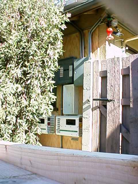
The modifications for solar input
Besides the physical installation of the panels described above, what we
did was basically to insert the inverter in between the meter and the
existing circuit breaker panel. This required minimal (basically no)
rewiring of the house and minimal modification to the existing circuit
breaker panel. The mains power from the grid goes through a 60A
circuit-breaker into the original panel, then from that panel to the
garage and the "AC-in" on the inverters. The house loads are connected
to a second circuit-breaker panel that is then connected to the "AC-out"
on the inverters.
Operation
If the panels are producing more power than we can use then the inverter
forces the extra back through the meter and onto the grid. If the
panels aren't producing enough, we suck power from the grid through the
meter and the inverter and into the house loads to make up the
difference. If the panels are producing no output and the batteries are
charged (as will typically be the case at night, for instance) then the
inverters will basically be a no-op. If the grid goes out - not that
that ever happens here in California, nooo ;) - then we pull power from
the panels and/or the batteries.
Net Metering
We can do this project because our power company has a "net metering"
plan for people who generate at least some of their own power. What
this means is that we pay for our electricity on a yearly "net" basis.
When we are producing a net surplus of power, we push the extra onto the
grid, running the meter backwards. When we are producing less than we
use, we pull the difference from the grid, running the meter forwards
again. The power company sends us a yearly bill for the net power we
have used for the year (or bill us for $0, and "pocket" the extra if we
produce more).
Batteries
By using the grid as our storage system in this manner, we can keep the
battery bank small, cheap, and easy to maintain. This should lower our
operational costs as well, since one of the major costs of solar power
is the maintenance (and replacement) of the power storage system that is
required to power things when there is no sun. Even so, running only on
batteries we have enough power to easily coast through a 2-hour
"rotating blackout", even with no help from the solar panels. If the
panels are getting sun and/or we cut back on our power usage then we
will be able to last correspondingly longer. If there is a major outage
of a day or more then we will likely run the batteries out of power, but
such a major outage is unlikely. Hopefully we will not have run the
batteries through too many charge/discharge cycles so they will last
longer than a set of batteries would normally as well.
We now have 4 of the general-purpose relays connected to bi-directional
solenoids rigged to flip the panel disconnect breakers (switches). The
inverters have been set to drive the relays to disconnect each section
of panels at different voltage levels on the DC (battery+panels) side,
and reconnect them once the voltage drops back down.
We have installed a transfer switch to swap the house between the inverters and
a direct-to-grid configuration. We did this mostly so that we could work on
the PV system without having to shut down the house (except for a momentary
outage as we flip the switch). The switch affects only what feeds the house -
grid or inverters - and does not affect the grid-interactivity of the
inverters. If we flip the house over to the direct grid connection the PV
system still remains connected to the grid as well, and can push power back to
the grid.
We just added some dedicated charge controllers to the system to protect the
batteries. This was something that we considered for the original design but
decided against because of cost. Since then there have been newer products
released that are both cheaper and can handle higher power installations. The
previous conficuration (above) had the inverters drive relays to disconnect the
panels from the batteries if the voltage coming off the panels drove the DC
voltage too high. This worked well, (and is still in place, actually) but
being mechanical we were concerned about the system eventually failing and/or
the relays being a maintenance issue.
The Bottom Line
To the above you have to add the price of one set of replacement batteries, the
transfer switch, and the charge controllers. The installed price for these
items were about $850, $150, and $800, respectively, bringing the total system
price to $33670.63.
The Future
How long it actually takes to pay off our system however depends on a number of
unknown factors. The "known unknowns" are things like the cost of maintenance
of the system, the future price of electricity, and our future energy usage.
Resource links...
Get in touch!
If you have any questions or would like to send me feedback about this
project please feel free to email me at
(or spamdump4242-solar at yahoo.com) with a subject of "solar
project" to get through my anti-spam filters.
This page intentionally graphics-deficient.
Last updated
December 15 2012 03:03:04